
-
Jiangsu Handing Machinery Co.,Ltd.
Changzhou Handing International Trading Co.,Ltd.
- 0086-13815079818
 Home > News
If you’re selecting a sheathing line for medium and large power cables, you’re likely weighing three things: diameter coverage, material compatibility, and stable quality at a cost your plant can sustain. This guide explains how an EXT150‑25DA extruder production line—configured with gantry pay‑off and gantry take‑up—covers 15–110 mm cable cores across PVC, PE, LSZH, and Nylon, while keeping concentricity steady with closed‑loop control and practical PLC recipes. I’ll share realistic ranges, commissioning habits, and preventive maintenance that keep uptime high without making the process feel like rocket science.
Note: In the first mention below, we reference our own product for context. The EXT150-25DA model discussed belongs to Handing Machinery.
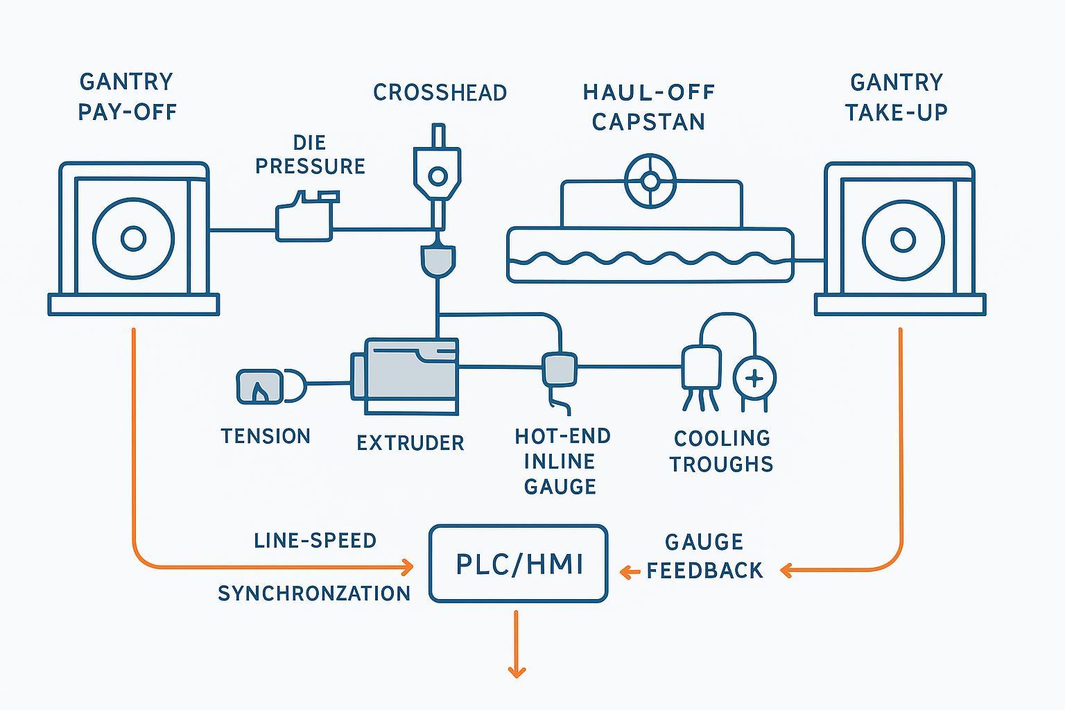
A well‑specified cable extrusion line for outer sheathing typically includes:
Gantry pay‑off with tension feedback and braking/servo control
150 mm single‑screw extruder with multi‑zone barrel heating, AC drive, and pressure/temperature sensing
Crosshead (jacketing die) with fine centering and gum‑space control
Hot‑end inline gauge (OD/ovality or multi‑layer measurement)
Multi‑stage cooling (spray + immersion) with temperature‑controlled water
Haul‑off/capstan with encoder feedback
Spark tester (when applicable) and marking/printing
Gantry take‑up with closed‑loop tension and traverse
Central PLC/HMI for recipe, synchronization, and alarms
Closed‑loop control links pay‑off, capstan, and take‑up tension to line speed and extruder output. Stabilizing entry tension and head pressure is one of the most effective ways to keep concentricity steady, surface finish smooth, and wall thickness within tolerance. Always align with plant safety practices (machine guarding, PPE, and lockout/tagout during tooling changes per OSHA‑style frameworks).
For power cable sheathing, the EXT150‑25DA extruder production line is planned around medium/large cores. Typical ranges you can plan for in daily production are below. Always verify against your exact tooling and formulations.
Table — Typical processing windows by material (guide values)
Material | Melt temp range (°C) | Key rheology notes | Cooling notes | Practical cautions |
|---|---|---|---|---|
PVC | 130–180 | Needs full plasticization without thermal degradation; balanced shear helps dispersion | Moderate quench; avoid thermal shock | Overheating causes discoloration; keep residence time reasonable |
PE (LD/MD/HD) | 160–220 | Wider drawdown; watch shear to avoid sharkskin | Longer cooling; water temp control improves finish | Density/grade shifts window; stabilize haul‑off |
LSZH (HFFR) | 155–175 | High filler loading → higher viscosity; minimize shear | Start with warmer water (≈30–40 °C) then cool | Excess heat can release bound water → voids/blisters |
Nylon (PA) | 220–260 | Moisture‑sensitive; pre‑dry thoroughly; notable die swell | Controlled quench to keep surface smooth | Humidity control is critical before and during run |
For diameter: plan sheath jobs over cable cores from 15 mm up to about 110 mm, with post‑sheath ODs typically ending in the 18–120 mm band depending on wall thickness. This covers common MV sheathing use cases while leaving headroom for thicker LSZH jackets at the upper end.
Where to learn more inside our site: the materials and applications overview in the wire & cable extrusion lines page provides additional background on compatible polymers and applications in a neutral, engineering tone. See the wire & cable extrusion lines overview from Handing Machinery: materials and process overview for wire & cable extrusion lines.
When you’re quoting or planning a run, these are the anchors engineers typically use on an EXT150‑25DA extruder production line:
Pre‑sheath cable core diameter: 15–110 mm (typical operating window)
Sheath thickness: about 1.2–5.0 mm depending on standard, environment class, and protection needs
Post‑sheath OD: generally 18–120 mm
Line speed: practical envelope from roughly 10–60 m/min depending on diameter, wall, and material
Concentricity target: plan for ≥97% on steady production with good centering and feedback; use inline measurement at both hot and cold ends to accelerate start‑up tuning
Thickness tolerance: many MV specifications accept local minima down to 80% of nominal as the lower bound; confirm per your governing standard
Spark testing: apply inline where applicable to detect pinholes and thin spots
Why these numbers matter: a large, stiff cable core entering the crosshead needs stable tension to prevent wandering; any wander shows as eccentricity and uneven wall. Closed‑loop tension and head‑pressure stabilization shrink that variance, making it easier to hold thickness and pass QA with fewer restarts.
For a concise public spec snapshot, review Handing Machinery’s article on this model: EXT150‑25DA extruder production line delivery highlights.
Concentricity is won or lost in the first minutes after start‑up and during ramps. The EXT150‑25DA extruder production line helps operators lock in the target quickly by combining:
Fine mechanical centering at the crosshead, so you can zero the wall with minimal turns
A die‑pressure loop that moderates screw rpm, reducing output oscillations that would otherwise thicken and thin the jacket
Hot‑end and cold‑end gauges that let you compare the fresh extrudate to the set jacket after cooling and adjust before scrap accumulates
Synchronized gantry pay‑off/take‑up tension so the core doesn’t wander as speeds change
Think of it this way: if entry tension and head pressure don’t drift, the melt cone in the head stays stable; a stable cone means the same wall thickness emerges from every quadrant of the die. That’s the simplest path to ≥97% concentricity in real production.
Table — Inline metrology at a glance (conceptual)
Technology | What it measures | Response time (typical) | Strengths | Limitations | Best use case |
|---|---|---|---|---|---|
Laser micrometer | OD and ovality | Milliseconds | Fast, simple integration, great for OD/ovality | Can’t resolve multilayer wall thickness directly | General OD control and start‑up verification |
X‑ray gauge | Wall thickness by quadrant, OD, eccentricity | Milliseconds | Sees wall distribution on thick jackets | Higher integration effort; shielding and calibration required | Large power cables and multilayer jackets |
Optical camera | Surface defects, diameter (derived) | Milliseconds | Visual surface QA and diameter proxy | Limited at high temperatures; not a wall gauge | Surface monitoring and defect detection |
On the EXT150‑25DA extruder production line, the PLC ties together four key loops:
Tension control on gantry pay‑off and gantry take‑up via load‑cell or dancer feedback (stability during accelerations/decelerations)
Line‑speed synchronization using encoders so haul‑off sets the pace and all axes track setpoints
Die‑pressure loop that trims screw rpm for steady output (reduces wall thickness swings)
Inline gauge feedback (OD/ovality or wall data) to guide centering and recipe tweaks during start‑up and diameter changes
Recipe examples (conceptual windows to start from; fine‑tune on site):
PVC jacket on 45 mm core to 52 mm OD: barrel 150–165–170–170 °C (rear→front), head 170–175 °C, screw 30–45 rpm, haul‑off to achieve 25–40 m/min depending on cooling length
LSZH jacket on 75 mm core to 84 mm OD: barrel 160–165–168–168 °C, head ≈165–170 °C, screw 25–38 rpm with gentle pressure rise, start with warmer first trough (≈35 °C), haul‑off 12–22 m/min
Quick changeover expectations on an EXT150‑25DA extruder production line:
Die insert change and re‑center to within spec: often achievable in 15–30 minutes with single‑point centering and a disciplined start‑up routine
Material change (PVC ↔ LSZH): plan 30–60 minutes including purge, temperature stabilization, and recipe switch; shorten with pre‑heated tooling and staged purge
These are realistic, operations‑driven ranges rather than marketing promises. The aim is to minimize scrap during transitions while keeping operators confident and safe.
Actual mass‑throughput depends on screw design, L/D, die back‑pressure, wall thickness, and cooling capacity. Use the table below as a planning envelope for a 150 mm single‑screw jacketing line; confirm onsite with your tooling and compound grades.
Table — Representative outputs and line speeds (guide ranges)
Material | Throughput (kg/h) typical | Line speed (m/min) typical | Caveats & notes |
|---|---|---|---|
PVC | 300–750 | 20–60 | Upper speeds at smaller OD/thinner walls; watch temperature stability to prevent discoloration |
PE (LD/MD) | 300–750 | 20–60 | Drawdown allows speed; avoid sharkskin via shear control and smooth cooling |
LSZH | 200–600 | 10–35 | High filler loading reduces mass rate; protect compound from overheating; warm‑start cooling |
Nylon (PA) | 300–750 | 15–45 | Pre‑dry thoroughly; manage die‑swell and cooling to maintain gloss and roundness |
Energy perspective: Specific energy per metric ton will vary with material temperature, screw rpm, and cooling load. Two levers consistently cut energy per produced meter: stabilize die pressure (less hunting → fewer scrap meters) and synchronize gantry tensions to reduce peaks during ramps. Smooth ramps also protect belts, bearings, and gearboxes—maintenance you don’t have to do saves energy indirectly.
Commissioning checklist (condensed)
Verify floor layout, utilities, and safety zones; level and align modules from pay‑off to take‑up
Dry run each axis, then heat‑soak zones; confirm thermocouple mapping and alarm limits
Install tooling; center crosshead mechanically; confirm gum‑space; install gauges and calibrate
Load recipe; set initial tensions and die‑pressure setpoints; stage purge material and cleaning tools
Start at low speed; tune centering with hot‑end gauge; verify thickness and OD against samples; enable spark test if applicable
Preventive maintenance cadence (high‑value items)
Daily: clean and inspect cooling troughs, check belt condition and encoder signals, test E‑stops and guards, confirm temperatures and die pressure trends match recipe
Weekly/monthly: lubricate moving parts per OEM schedule, check dancer/load‑cell calibration, inspect haul‑off belts/rollers and traverse screws, descale heat exchangers if water quality is hard
2,500–5,000 h: inspect screw/barrel wear, gearbox oil analysis, haul‑off drive alignment, gauge recalibration, vibration analysis on motors and bearings; replace parts at wear limits
For deeper troubleshooting patterns and corrective actions, see Handing Machinery’s guide: troubleshooting common cable extrusion issues.
Symptoms you may see and what they often mean:
Eccentric wall (thick/thin opposite sides): crosshead not centered, unstable entry tension, or conductor wander; correct by re‑centering, stabilizing pay‑off tension, and checking haul‑off speed stability
Ovality and ripple marks: uneven cooling or haul‑off slippage; verify trough temperatures and belt pressure, and inspect capstan lining
Surface pitting or blisters (LSZH): moisture release from fillers due to excessive heat or inadequate pre‑drying; reduce shear heat and raise initial water temperature
Gloss variation or sharkskin (PE): excessive shear at the die; reduce screw rpm/pressure, polish die land, and soften quench
Burn marks (PVC): local overheating or dead spots; balance temperatures and inspect for stagnation in the head
Keep a record of setpoints and results for each material/diameter so your team can converge faster next time. It’s amazing how a disciplined logbook shrinks start‑up scrap.
Here’s a replicable, conservative workflow that many teams adopt on an EXT150‑25DA extruder production line. Treat values as starting windows—optimize to your tooling and compound.
Before stop: reduce screw rpm and line speed gradually, hold die pressure stable, then purge with a neutral compound if available
Tooling: pre‑heat head/die inserts for LSZH; confirm die land suitable for final OD ≈ 90 mm
Temperatures: set barrel zones ≈160–168 °C and head ≈165–170 °C (compound‑specific)
Cooling: set first trough ≈35 °C to avoid thermal shock, second stage at lower temperature for final set
Tension: lower pay‑off and take‑up tension setpoints by 5–10% versus PVC to reduce conductor wander during the slower, more viscous run
Start‑up: run at 10–15 m/min, center using hot‑end gauge, sample and verify wall thickness; ramp to 18–25 m/min as cooling allows
Time budget: 30–60 minutes total, with 10–20 minutes for purge and 10–20 minutes for centering/QA; plan 1–3 scrap coils depending on QA regime
This approach keeps the system within safe thermal limits for LSZH and prioritizes steady tension, which is usually where concentricity wins are made.
For MV/HV sheathing work, align your QA with the applicable construction and test standards. Commonly referenced frameworks include:
IEC 60502‑1/‑2 for power cables up to 30 kV: sheath construction, minimum thickness, and routine tests; many specs interpret local minima as ≥80% of nominal (confirm in your project SOW)
IEC 60840 for >30–150 kV constructions: additional requirements for HV
IEC 62230 spark test for detecting insulation/sheath defects inline
From the plant perspective, the essentials are: verify OD/ovality continuously, measure thickness and concentricity on start‑up and at intervals, run spark testing where applicable, log results, and keep a clean trail for audits.
For large‑diameter lines and gantry options, see Handing Machinery’s overview: big‑size cable sheathing and gantry pay‑off/take‑up options. For general context about delivered systems and factory readiness, the news/category feed offers examples of installed equipment and start‑ups: recent deliveries and capability news. For a concise model snapshot, refer to: EXT150‑25DA extruder production line delivery highlights.
If you want a configuration built around your exact wall thicknesses, materials, and QA regime, request a line layout or a sample PLC recipe tuned to your diameters. For a broader look at materials and extrusion concepts, start with the overview page: wire & cable extrusion lines: materials and applications. To explore gantry options and floor‑space planning for large cables, visit: big‑size cable sheathing line with gantry modules.
The EXT150‑25DA extruder production line is designed to give engineers a predictable window for 15–110 mm power cable sheathing across PVC, PE, LSZH, and Nylon—backed by closed‑loop synchronization, practical recipes, and maintenance routines your team can live with day after day.


 +86-13815079818
 0086-13815079818


